Seguridad y Redes

Tips, Video Tutoriales, Wifislax, VMware, Linux, GNS3, Eve-NG, CCNA, Cisco Routers, Switches

Frame Relay con Inverse ARP

Con esta practica en GNS3, verificaremos y entenderemos el funcionamiento de Frame Relay. Esta tecnologia WAN (Wide Area Network) es muy popular porque facilita la construcción de redes confiables y de bajo costo. Uno de sus principales ventajas es de poder configurar enlaces seriales punto a punto con la capacidad de conectar un sitio a muchos sitios remotos a través de un circuito físico. En esta practica se mostrara el proceso de la configuración de Frame Relay utilizando la siguiente topologia.

Topologia de Frame Relay a Configurar en GNS3.

La imagen anterior muestra una topologia Full Mesh. Una red Mesh es una red múltiplemente conexa, en la cual los nodos tienen más de una conexión con más de un nodo diferente. No necesariamente deben conectarse todos contra todos, éste es un caso especial que se denomina Full-Mesh. Configuraremos esta topologia en GNS3, en el cual utilizaremos un Router central el cual le configuraremos cuatro interfaces seriales donde le indiciaremos los DLCIs para que puedan ser asignados dinamicamente con Inverse ARP. Al configurar la encapsulacion Frame Relay en cada Router, automaticamente detectara los DLCIs ya que Inverse ARP esta habilitado por defecto.

Frame Relay en GNS3 con topologia Full Mesh.

Para configurar esta toplogia primero realizaremos la configuracion del Switch de Frame Relay, donde le indicaremos los DLCIs. Lo primero es activar la conmutación Frame Relay en el Router con el siguiente comando.

FrameRelay(config)#frame-relay switching

Luego a configurar las interfaces seriales, la encapsulacion, el reloj, le indicaremos que la interface como dispositivo DCE y por ultimo definimos los DLCIs para cada interface.

FrameRelay#configure terminal
FrameRelay(config)#interface Serial1/0
FrameRelay(config-if)#no ip address
FrameRelay(config-if)#encapsulation frame-relay
FrameRelay(config-if)#clock rate 64000
FrameRelay(config-if)#frame-relay intf-type dce
FrameRelay(config-if)#frame-relay route 102 interface Serial1/1 201
FrameRelay(config-if)#frame-relay route 103 interface Serial1/2 301
FrameRelay(config-if)#frame-relay route 104 interface Serial1/3 401
FrameRelay(config-if)#no shutdown
FrameRelay(config-if)#exit
FrameRelay(config)#interface Serial1/1
FrameRelay(config-if)#no ip address
FrameRelay(config-if)#encapsulation frame-relay
FrameRelay(config-if)#clock rate 64000
FrameRelay(config-if)#frame-relay intf-type dce
FrameRelay(config-if)#frame-relay route 201 interface Serial1/0 102
FrameRelay(config-if)#frame-relay route 203 interface Serial1/2 302
FrameRelay(config-if)#frame-relay route 204 interface Serial1/3 402
FrameRelay(config-if)#no shutdown
FrameRelay(config-if)#exit
FrameRelay(config)#interface Serial1/2
FrameRelay(config-if)#no ip address
FrameRelay(config-if)#encapsulation frame-relay
FrameRelay(config-if)#clock rate 64000
FrameRelay(config-if)#frame-relay intf-type dce
FrameRelay(config-if)#frame-relay route 301 interface Serial1/0 103
FrameRelay(config-if)#frame-relay route 302 interface Serial1/1 203
FrameRelay(config-if)#frame-relay route 304 interface Serial1/3 403
FrameRelay(config-if)#no shutdown
FrameRelay(config-if)#exit
FrameRelay(config)#interface Serial1/3
FrameRelay(config-if)#no ip address
FrameRelay(config-if)#encapsulation frame-relay
FrameRelay(config-if)#clock rate 64000
FrameRelay(config-if)#frame-relay intf-type dce
FrameRelay(config-if)#frame-relay route 401 interface Serial1/0 104
FrameRelay(config-if)#frame-relay route 402 interface Serial1/1 204
FrameRelay(config-if)#frame-relay route 403 interface Serial1/2 304
FrameRelay(config-if)#no shutdown
FrameRelay(config-if)#exit
FrameRelay(config)#end
FrameRelay#
Ahora configuramos las interfaces de los Routers.
R1>enable
R1#configure terminal
R1(config)# interface serial1 /0
R1(config-if)#encapsulation frame-relay
R1(config-if)#frame-relay lmi-type cisco
R1(config-if)#ip address 192.168.123.1 255.255.255.0
R1(config-if)#no shutdown
R1(config-if)#end
R1#
R2>enable
R2#configure terminal
R2(config)#interface serial1/0
R2(config-if)#encapsulation frame-relay
R2(config-if)#frame-relay lmi-type cisco
R2(config-if)#ip address 192.168.123.2 255.255.255.0
R2(config-if)#no shutdown
R2(config-if)#end
R2#
R3>enable
R3#configure terminal
R3(config)#interface serial1/0
R3(config-if)#encapsulation frame-relay
R3(config-if)#frame-relay lmi-type cisco
R3(config-if)#ip address 192.168.123.3 255.255.255.0
R3(config-if)#no shutdown
R3(config-if)#end
R3#
R4>enable
R4#configure terminal
R4(config)#interface serial1/0
R4(config-if)#encapsulation frame-relay
R4(config-if)#frame-relay lmi-type cisco
R4(config-if)#ip address 192.168.123.4 255.255.255.0
R4(config-if)#no shutdown
R4(config-if)#end
R4#
Terminando de realizar lo anterior ya podemos verificar en cualquier router con el comando show frame-relay pvc que Inverse ARP ha realizado su trabajo.
R1#show frame-relay pvc

PVC Statistics for interface Serial1/0 (Frame Relay DTE)

              Active     Inactive      Deleted       Static
  Local          3            0            0            0
  Switched       0            0            0            0
  Unused         0            0            0            0

DLCI = 102, DLCI USAGE = LOCAL, PVC STATUS = ACTIVE, INTERFACE = Serial1/0

  input pkts 1             output pkts 1            in bytes 34      
  out bytes 34             dropped pkts 0           in pkts dropped 0        
  out pkts dropped 0                out bytes dropped 0        
  in FECN pkts 0           in BECN pkts 0           out FECN pkts 0        
  out BECN pkts 0          in DE pkts 0             out DE pkts 0        
  out bcast pkts 1         out bcast bytes 34      
  5 minute input rate 0 bits/sec, 0 packets/sec
  5 minute output rate 0 bits/sec, 0 packets/sec
  pvc create time 00:07:06, last time pvc status changed 00:06:46
         
DLCI = 103, DLCI USAGE = LOCAL, PVC STATUS = ACTIVE, INTERFACE = Serial1/0

  input pkts 1             output pkts 2            in bytes 34      
  out bytes 68             dropped pkts 0           in pkts dropped 0        
  out pkts dropped 0                out bytes dropped 0        
  in FECN pkts 0           in BECN pkts 0           out FECN pkts 0        
  out BECN pkts 0          in DE pkts 0             out DE pkts 0        
  out bcast pkts 2         out bcast bytes 68      
  5 minute input rate 0 bits/sec, 0 packets/sec
  5 minute output rate 0 bits/sec, 0 packets/sec
  pvc create time 00:07:10, last time pvc status changed 00:06:50
         
DLCI = 104, DLCI USAGE = LOCAL, PVC STATUS = ACTIVE, INTERFACE = Serial1/0

  input pkts 1             output pkts 1            in bytes 34      
  out bytes 34             dropped pkts 0           in pkts dropped 0        
  out pkts dropped 0                out bytes dropped 0        
  in FECN pkts 0           in BECN pkts 0           out FECN pkts 0        
  out BECN pkts 0          in DE pkts 0             out DE pkts 0        
  out bcast pkts 1         out bcast bytes 34      
  5 minute input rate 0 bits/sec, 0 packets/sec
  5 minute output rate 0 bits/sec, 0 packets/sec
  pvc create time 00:07:11, last time pvc status changed 00:06:41
Muestra estadísticas acerca de los PVC para las interfaces.

Como podemos ver, Inverse ARP ha detectado los DLCIs. Como se muestra en la salida anterior ha detectado 3 DLCIs en funcionamiento. Estas DLCIs son las que tenemos en nuestra topologia. Para verificar el funcionamiento de Frame Relay podemos también utilizar los siguientes comandos.
Las Estadisticas de los LMI.
R1#show frame-relay lmi
LMI Statistics for interface Serial1/0 (Frame Relay DTE) LMI TYPE = CISCO
  Invalid Unnumbered info 0             Invalid Prot Disc 0
  Invalid dummy Call Ref 0              Invalid Msg Type 0
  Invalid Status Message 0              Invalid Lock Shift 0
  Invalid Information ID 0              Invalid Report IE Len 0
  Invalid Report Request 0              Invalid Keep IE Len 0
  Num Status Enq. Sent 140              Num Status msgs Rcvd 115
  Num Update Status Rcvd 0              Num Status Timeouts 25
  Last Full Status Req 00:00:00         Last Full Status Rcvd 00:00:00

El mapeo de los DLCIs.
R1#show frame-relay map
Serial1/0 (up): ip 192.168.123.2 dlci 102(0x66,0x1860), dynamic,
              broadcast,, status defined, active
Serial1/0 (up): ip 192.168.123.3 dlci 103(0x67,0x1870), dynamic,
              broadcast,, status defined, active
Serial1/0 (up): ip 192.168.123.4 dlci 104(0x68,0x1880), dynamic,
              broadcast,, status defined, active0
Muestra las entradas de mapeo actuales.

En la salida anterior nos muestra los DLCIs y que han sido aprendidos de manera dinámica. Con el siguiente comando podemos verificar que estamos utilizando la encapsulación de frame-relay en la interface, los datos de LMI, los Keepalive y mas informacion sobre la interface.
R1#show interface serial1/0
Serial1/0 is up, line protocol is up
  Hardware is M4T
  Internet address is 192.168.123.1/24
  MTU 1500 bytes, BW 1544 Kbit, DLY 20000 usec,
     reliability 255/255, txload 1/255, rxload 1/255
  Encapsulation FRAME-RELAY, crc 16, loopback not set
  Keepalive set (10 sec)
  Restart-Delay is 0 secs
  CRC checking enabled
  LMI enq sent  105, LMI stat recvd 80, LMI upd recvd 0, DTE LMI up
  LMI enq recvd 0, LMI stat sent  0, LMI upd sent  0
  LMI DLCI 1023  LMI type is CISCO  frame relay DTE
  FR SVC disabled, LAPF state down
  Broadcast queue 0/64, broadcasts sent/dropped 5/0, interface broadcasts 0
  Last input 00:00:06, output 00:00:06, output hang never
  Last clearing of "show interface" counters 00:18:53
  Input queue: 0/75/0/0 (size/max/drops/flushes); Total output drops: 0
  Queueing strategy: weighted fair
  Output queue: 0/1000/64/0 (size/max total/threshold/drops)
     Conversations  0/1/256 (active/max active/max total)
     Reserved Conversations 0/0 (allocated/max allocated)
     Available Bandwidth 1158 kilobits/sec
  5 minute input rate 0 bits/sec, 0 packets/sec
  5 minute output rate 0 bits/sec, 0 packets/sec
     85 packets input, 1618 bytes, 0 no buffer
     Received 0 broadcasts, 0 runts, 0 giants, 0 throttles
     0 input errors, 0 CRC, 0 frame, 0 overrun, 0 ignored, 0 abort
     114 packets output, 1671 bytes, 0 underruns
     0 output errors, 0 collisions, 1 interface resets
     0 output buffer failures, 0 output buffers swapped out
     1 carrier transitions     DCD=up  DSR=up  DTR=up  RTS=up  CTS=up
Encapsulacion Frame Relay en la Interface Serial.

Verificamos la conectividad dando un ping a cada router.
R1#ping 192.168.123.2

Type escape sequence to abort.
Sending 5, 100-byte ICMP Echos to 192.168.123.2, timeout is 2 seconds:
!!!!!
Success rate is 100 percent (5/5), round-trip min/avg/max = 28/142/332 ms
R1#ping 192.168.123.3

Type escape sequence to abort.
Sending 5, 100-byte ICMP Echos to 192.168.123.3, timeout is 2 seconds:
!!!!!
Success rate is 100 percent (5/5), round-trip min/avg/max = 56/120/192 ms
R1#ping 192.168.123.4

Type escape sequence to abort.
Sending 5, 100-byte ICMP Echos to 192.168.123.4, timeout is 2 seconds:
!!!!!
Success rate is 100 percent (5/5), round-trip min/avg/max = 64/127/240 ms


Algunas pagina en linea para practicar Subnetting y VLSM!!

https://www.subnettingquestions.com/ http://www.kehlet.cx/docs/2004/03/subnet.php http://faculty.valleycollege.net/rpowell/jscript/subnet2.htm http://www.semsim.com/ccna/tutorial/subnetting/subnetting.html http://www.gt-solutions.com/subnet-1.php http://www.techexams.net/ip-subnet-calculator/ http://www.networking-forum.com/practicesubnetting.php http://www.networking-forum.com/subnet_calculator.php

Rutas Conectadas y Rutas Estáticas

Los Routers necesitan tener rutas en sus tablas de enrutamiento IP para poder enviar los paquetes a la direcciónes correctas. Dos formas por el cual un router agrega rutas en su tabla de enrutamiento es aprendiendo o se da cuenta que redes tiene conectadas en sus interfaces y otra forma es mediante la configuración de las rutas desde la configuración global. La siguiente imagen muestra una topologia básica para configurar rutas estáticas.

Topologia Básica de la Red.

En GNS3, la topologia de rede se vería mas o menos de la siguiente manera.

Topologia de Red en GNS3.

Rutas Conectadas.


Configuración de las interfaces en el Router1
!
interface FastEthernet0/0
ip address 10.1.128.251 255.255.255.0
duplex auto
speed auto
!
interface FastEthernet0/1
ip address 10.1.130.251 255.255.255.0
duplex auto
speed auto
!
interface FastEthernet1/0
ip address 10.1.1.251 255.255.255.0
duplex auto
speed auto
!
El comando siguiente muestras el estado de las interfaces en el Router1, como se puede ver las tres interfaces están en estado "up & up" y cada interface tiene configurado una dirección IP.
Router1#show ip int brief
Interface                  IP-Address      OK? Method Status                Protocol
FastEthernet0/0            10.1.128.251    YES manual up                    up
FastEthernet0/1            10.1.130.251    YES manual up                    up
FastEthernet1/0            10.1.1.251      YES manual up                    up
Router1#
El siguiente comando nos muestra las rutas conocidas por el Router1, todas las rutas conectadas (C).
Router1#show ip route
Codes: C - connected, S - static, R - RIP, M - mobile, B - BGP
D - EIGRP, EX - EIGRP external, O - OSPF, IA - OSPF inter area
N1 - OSPF NSSA external type 1, N2 - OSPF NSSA external type 2
E1 - OSPF external type 1, E2 - OSPF external type 2
i - IS-IS, su - IS-IS summary, L1 - IS-IS level-1, L2 - IS-IS level-2
ia - IS-IS inter area, * - candidate default, U - per-user static route
o - ODR, P - periodic downloaded static route

Gateway of last resort is not set

10.0.0.0/24 is subnetted, 3 subnets
C       10.1.1.0 is directly connected, FastEthernet1/0
C       10.1.130.0 is directly connected, FastEthernet0/1
C       10.1.128.0 is directly connected, FastEthernet0/0
Router1#
El Router1 agrego las rutas de las tres subredes que se encuentran conectadas a su tabla de enrutamiento. La letra "C" significa "Conectado".

Rutas Estáticas

Las rutas conectadas son importantes, pero los routers suelen necesitar de otras rutas para enviar la información a todas las subredes de una red. Por ejemplo el Router1 puede fácilmente realizar un Ping a las subredes que tiene conectadas, por ejemplo a la subred conectada 10.1.1.0/24. Sin embargo si se realiza un Ping a la subred 10.1.2.0/24 no la conocerá y no podrá llegar a esa subred. Tal como se muestra a continuación.

Ping a la subred conectada, interface Fa0/0 del Router2.
Router1#ping 10.1.128.252

Type escape sequence to abort.
Sending 5, 100-byte ICMP Echos to 10.1.128.252, timeout is 2 seconds:
!!!!!
Success rate is 100 percent (5/5), round-trip min/avg/max = 20/60/116 ms
Router1#
Ping a la Subred 10.1.2.0/24.
Router1#ping 10.1.2.252

Type escape sequence to abort.
Sending 5, 100-byte ICMP Echos to 10.1.2.252, timeout is 2 seconds:
.....
Success rate is 0 percent (0/5)
Router1#
El comando Ping envía un paquete de solicitud ICMP (echo request) a la dirección destino. El host destino responde al ping solicitado con un paquete llamada ICMP de respuesta o echo reply. El comando Ping envía el primer paquete y espera la respuesta. Si se recibe una respuesta, el comando muestra un "!". Si no se recibe una respuesta en el tiempo de espera predeterminado de 2 segundos, el comando ping nos muestra un ".". En el IOS de cisco, el comando Ping envía cinco de estos paquetes de forma predeterminada. En el ejemplo anterior el primer Ping dado a la IP 10.1.128.252 funciona correctamente, ya que nos muestra todos los "!!!!!". Sin embargo, el Ping dado a la dirección IP 10.1.2.252 no funciona, ya que nos muestra todo los ".....", esto es porque el Router1 no tiene una ruta para la subred 10.1.2.0/24 donde se encuentra la IP 10.1.2.252.

La solución mas sencilla y típica para este problema es configurar un protocolo de enrutamiento en los tres Routers. Sin embargo, en lugar de protocolos de enrutamientos, podemos configurar rutas estáticas. Para configurar rutas estáticas se realiza de la siguiente manera.

Configurando Rutas Estáticas en el Router1.
Router1#configure terminal
Router1(config)#ip route 10.1.2.0 255.255.255.0 10.1.128.252
Router1(config)#ip route 10.1.3.0 255.255.255.0 10.1.130.252
Router1(config)#^Z
Router1#
*Mar  1 00:11:14.279: %SYS-5-CONFIG_I: Configured from console by console
Router1#show ip route static
10.0.0.0/24 is subnetted, 5 subnets
S       10.1.3.0 [1/0] via 10.1.130.252
S       10.1.2.0 [1/0] via 10.1.128.252
Router1#
Desde configuración global le indicamos cual sera la subred con su respectiva mascara y la dirección IP del siguiente salto. Ahora el Router1 sabe como enviar las rutas a los demás Routers de la Red. También se muestra el comando show ip route static, con el podemos visualizar que rutas estáticas tenemos configuradas en el Router1. El Signo de "S" significa que la ruta fue configurada estaticamente.

Ping a las demás Subredes.
Router1#ping 10.1.2.252
Type escape sequence to abort.
Sending 5, 100-byte ICMP Echos to 10.1.2.252, timeout is 2 seconds:
!!!!!
Success rate is 100 percent (5/5), round-trip min/avg/max = 8/56/132 ms

Router1#ping 10.1.3.253
Type escape sequence to abort.
Sending 5, 100-byte ICMP Echos to 10.1.3.253, timeout is 2 seconds:
!!!!!
Success rate is 100 percent (5/5), round-trip min/avg/max = 8/44/136 ms
Router1#
Visualizar todas las rutas en el Router1.
Router1#show ip route
Codes: C - connected, S - static, R - RIP, M - mobile, B - BGP
D - EIGRP, EX - EIGRP external, O - OSPF, IA - OSPF inter area
N1 - OSPF NSSA external type 1, N2 - OSPF NSSA external type 2
E1 - OSPF external type 1, E2 - OSPF external type 2
i - IS-IS, su - IS-IS summary, L1 - IS-IS level-1, L2 - IS-IS level-2
ia - IS-IS inter area, * - candidate default, U - per-user static route
o - ODR, P - periodic downloaded static route

Gateway of last resort is not set

10.0.0.0/24 is subnetted, 5 subnets
S       10.1.3.0 [1/0] via 10.1.130.252
S       10.1.2.0 [1/0] via 10.1.128.252
C       10.1.1.0 is directly connected, FastEthernet1/0
C       10.1.130.0 is directly connected, FastEthernet0/1
C       10.1.128.0 is directly connected, FastEthernet0/0
Router1#
Como se puede observar tenemos comunicación con las subredes configuradas, esto solo desde el Router1. En los demás Routers se tiene que hacer el mismo proceso para configurar las rutas estáticas y así tener comunicación con las demás subredes.

Configuración de Frame Relay

Frame Relay es un protocolo WAN muy popular porque facilita la construcción de redes confiables y de bajo costo. Uno de sus principales ventajas es de poder configurar enlaces seriales punto a punto con la capacidad de conectar un sitio a muchos sitios remotos a través de un circuito físico. En este post se mostrara la configuración de Frame Relay utilizando la siguiente topologia.
Empecemos configurando el primer Router
Router1#conf t
Enter configuration commands, one per line.  End with CNTL/Z.
Router1(config)#int s1/0
Router1(config-if)#ip address 192.168.1.1 255.255.255.248
Router1(config-if)#encapsulation frame-relay
Router1(config-if)#no frame-relay inverse-arp
Router1(config-if)#frame-relay map ip 192.168.1.2 102 broadcast
Router1(config-if)#frame-relay map ip 192.168.1.3 103 broadcast
Router1(config-if)#no shut
Router1(config-if)#
*Mar  1 00:11:15.775: %LINK-3-UPDOWN: Interface Serial1/0, changed state to up
Router1(config-if)#
*Mar  1 00:11:26.775: %LINEPROTO-5-UPDOWN: Line protocol on Interface Serial1/0, changed state to up
Router1(config-if)#end
Router1#
Hacemos lo mismo con el Router2
Router2#conf t
Enter configuration commands, one per line.  End with CNTL/Z.
Router2(config)#int s1/0
Router2(config-if)#ip address 192.168.1.2 255.255.255.248
Router2(config-if)#encapsulation frame-relay
Router2(config-if)#no frame-relay inverse-arp
Router2(config-if)#frame-relay map ip 192.168.1.1 201 broadcast
Router2(config-if)#frame-relay map ip 192.168.1.3 201    
Router2(config-if)#no shut
Router2(config-if)#
*Mar  1 00:11:01.831: %LINK-3-UPDOWN: Interface Serial1/0, changed state to up
Router2(config-if)#
*Mar  1 00:11:12.831: %LINEPROTO-5-UPDOWN: Line protocol on Interface Serial1/0, changed state to up
Router2(config-if)#end
Router2#
Finalmente la configuracion del Router3
Router3#conf t
Enter configuration commands, one per line.  End with CNTL/Z.
Router3(config)#int s1/0
Router3(config-if)#ip address 192.168.1.3 255.255.255.248
Router3(config-if)#encapsulation frame-relay
Router3(config-if)#no frame-relay inverse-arp
Router3(config-if)#frame-relay map ip 192.168.1.1 301 broadcast
Router3(config-if)#frame-relay map ip 192.168.1.2 301   
Router3(config-if)#no shut
Router3(config-if)#
*Mar  1 00:11:33.187: %LINK-3-UPDOWN: Interface Serial1/0, changed state to up
Router3(config-if)#
*Mar  1 00:11:44.187: %LINEPROTO-5-UPDOWN: Line protocol on Interface Serial1/0, changed state to up
Router3(config-if)#
Router3(config-if)#end
Router3#
Mostrar el estado de la interface serial1/0 en el Router3
Router3#show ip int brief
Interface                  IP-Address      OK? Method Status                Protocol
FastEthernet0/0            unassigned      YES unset  administratively down down
FastEthernet0/1            unassigned      YES unset  administratively down down
Serial1/0                  192.168.1.3     YES manual up                    up
Serial1/1                  unassigned      YES unset  administratively down down
Serial1/2                  unassigned      YES unset  administratively down down
Serial1/3                  unassigned      YES unset  administratively down down
Realizar una prueba de conectividad.
Router3#ping 192.168.1.1
Type escape sequence to abort.
Sending 5, 100-byte ICMP Echos to 192.168.1.1, timeout is 2 seconds:
!!!!!
Success rate is 100 percent (5/5), round-trip min/avg/max = 16/73/132 ms
Router3#ping 192.168.1.2
Type escape sequence to abort.
Sending 5, 100-byte ICMP Echos to 192.168.1.2, timeout is 2 seconds:
!!!!!
Success rate is 100 percent (5/5), round-trip min/avg/max = 16/105/344 ms
Router3#
Mostrar el estado de la interface serial1/0 en el Router2
Router2#show ip int brief
Interface                  IP-Address      OK? Method Status                Protocol
FastEthernet0/0            unassigned      YES unset  administratively down down
FastEthernet0/1            unassigned      YES unset  administratively down down
Serial1/0                  192.168.1.2     YES manual up                    up
Serial1/1                  unassigned      YES unset  administratively down down
Serial1/2                  unassigned      YES unset  administratively down down
Serial1/3                  unassigned      YES unset  administratively down down
Realizar una prueba de conectividad.
Router2#ping 192.168.1.1
Type escape sequence to abort.
Sending 5, 100-byte ICMP Echos to 192.168.1.1, timeout is 2 seconds:
!!!!!
Success rate is 100 percent (5/5), round-trip min/avg/max = 8/63/148 ms
Router2#ping 192.168.1.3
Type escape sequence to abort.
Sending 5, 100-byte ICMP Echos to 192.168.1.3, timeout is 2 seconds:
!!!!!
Success rate is 100 percent (5/5), round-trip min/avg/max = 12/127/276 ms
Router2#
Verificacamos la misma informacion en el Router1
Router1#show ip int brief
Interface                  IP-Address      OK? Method Status                Protocol
FastEthernet0/0            unassigned      YES unset  administratively down down
FastEthernet0/1            unassigned      YES unset  administratively down down
Serial1/0                  192.168.1.1     YES manual up                    up
Serial1/1                  unassigned      YES unset  administratively down down
Serial1/2                  unassigned      YES unset  administratively down down
Serial1/3                  unassigned      YES unset  administratively down down

Router1#ping 192.168.1.2
Type escape sequence to abort.
Sending 5, 100-byte ICMP Echos to 192.168.1.2, timeout is 2 seconds:
!!!!!
Success rate is 100 percent (5/5), round-trip min/avg/max = 8/56/140 ms
Router1#ping 192.168.1.3
Type escape sequence to abort.
Sending 5, 100-byte ICMP Echos to 192.168.1.3, timeout is 2 seconds:
!!!!!
Success rate is 100 percent (5/5), round-trip min/avg/max = 8/60/140 ms
Router1#
Información de encapsulacion y otros datos de la interface serial1/0
Router1#show interfaces serial1/0
Serial1/0 is up, line protocol is up
 Hardware is M4T
 Internet address is 192.168.1.1/29
 MTU 1500 bytes, BW 1544 Kbit, DLY 20000 usec,
    reliability 255/255, txload 1/255, rxload 1/255
 Encapsulation FRAME-RELAY, crc 16, loopback not set
 Keepalive set (10 sec)
 Restart-Delay is 0 secs
 LMI enq sent  44, LMI stat recvd 45, LMI upd recvd 0, DTE LMI up
 LMI enq recvd 0, LMI stat sent  0, LMI upd sent  0
 LMI DLCI 0  LMI type is ANSI Annex D  frame relay DTE
 Broadcast queue 0/64, broadcasts sent/dropped 0/0, interface broadcasts 0
 Last input 00:00:00, output 00:00:00, output hang never
 Last clearing of "show interface" counters 00:08:52
 Input queue: 0/75/0/0 (size/max/drops/flushes); Total output drops: 0
 Queueing strategy: weighted fair
 Output queue: 0/1000/64/0 (size/max total/threshold/drops)
    Conversations  0/1/256 (active/max active/max total)
    Reserved Conversations 0/0 (allocated/max allocated)
    Available Bandwidth 1158 kilobits/sec
 5 minute input rate 0 bits/sec, 0 packets/sec
 5 minute output rate 0 bits/sec, 0 packets/sec
    85 packets input, 4870 bytes, 0 no buffer
    Received 0 broadcasts, 0 runts, 0 giants, 0 throttles
    0 input errors, 0 CRC, 0 frame, 0 overrun, 0 ignored, 0 abort
    89 packets output, 4936 bytes, 0 underruns
    0 output errors, 0 collisions, 1 interface resets
    0 output buffer failures, 0 output buffers swapped out
    1 carrier transitions     DCD=up  DSR=up  DTR=up  RTS=up  CTS=up
Router1#
Estadísticas LMI
Router1#show frame-relay lmi

LMI Statistics for interface Serial1/0 (Frame Relay DTE) LMI TYPE = ANSI
Invalid Unnumbered info 0             Invalid Prot Disc 0
Invalid dummy Call Ref 0              Invalid Msg Type 0
Invalid Status Message 0              Invalid Lock Shift 0
Invalid Information ID 0              Invalid Report IE Len 0
Invalid Report Request 0              Invalid Keep IE Len 0
Num Status Enq. Sent 51               Num Status msgs Rcvd 52
Num Update Status Rcvd 0              Num Status Timeouts 0
Last Full Status Req 00:00:36         Last Full Status Rcvd 00:00:36
El siguiente comando muestra el estado y varias estadísticas útiles de cada uno de los PVC (Permanent Virtual Circuits).
Router1#show frame-relay pvc

PVC Statistics for interface Serial1/0 (Frame Relay DTE)

       Active     Inactive      Deleted       Static
Local          2            0            0            0
Switched       0            0            0            0
Unused         0            0            0            0

DLCI = 102, DLCI USAGE = LOCAL, PVC STATUS = ACTIVE, INTERFACE = Serial1/0

input pkts 20            output pkts 21           in bytes 2080
out bytes 2140           dropped pkts 0           in pkts dropped 0  
out pkts dropped 0                out bytes dropped 0  
in FECN pkts 0           in BECN pkts 0           out FECN pkts 0  
out BECN pkts 0          in DE pkts 0             out DE pkts 0  
out bcast pkts 0         out bcast bytes 0  
5 minute input rate 0 bits/sec, 0 packets/sec
5 minute output rate 0 bits/sec, 0 packets/sec
pvc create time 00:09:11, last time pvc status changed 00:07:44

DLCI = 103, DLCI USAGE = LOCAL, PVC STATUS = ACTIVE, INTERFACE = Serial1/0

input pkts 20            output pkts 21           in bytes 2080
out bytes 2140           dropped pkts 0           in pkts dropped 0  
out pkts dropped 0                out bytes dropped 0  
in FECN pkts 0           in BECN pkts 0           out FECN pkts 0  
out BECN pkts 0          in DE pkts 0             out DE pkts 0  
out bcast pkts 0         out bcast bytes 0  
5 minute input rate 0 bits/sec, 0 packets/sec
5 minute output rate 0 bits/sec, 0 packets/sec
pvc create time 00:08:52, last time pvc status changed 00:07:45
Información de los mapas actuales
Router1#show frame-relay map
Serial1/0 (up): ip 192.168.1.2 dlci 102(0x66,0x1860), static,
       broadcast,
       CISCO, status defined, active
Serial1/0 (up): ip 192.168.1.3 dlci 103(0x67,0x1870), static,
       broadcast,
       CISCO, status defined, active
Estadisticas de trafico
Router1#show frame-relay traffic
Frame Relay statistics:
 ARP requests sent 0, ARP replies sent 0
 ARP request recvd 0, ARP replies recvd 0
Router1#
Para configurar y monitorizar el router utilizando una transferencia segura de datos en el navegador, la solución es habilitar HTTPS (Hypertext Transfer Protocol Secure o en español Protocolo seguro de transferencia de hipertexto) en el router. Para habilitar HTTPS en un router cisco se utiliza el comando ip http secure-server.
Router#configure terminal
Enter configuration commands, one per line.  End with CNTL/Z.
Router(config)#ip http secure-server
% Generating 1024 bit RSA keys, keys will be non-exportable...[OK]
Router(config)#end
Router#
HTTPS nos proporciona un método seguro y encriptado para acceder al router desde un navegador web usando Secure Sockets Layer (Protocolo de Capa de Conexión Segura SSL) y Transport Layer Security (Seguridad de la Capa de Transporte TLS). Por defecto, el router crea un certificado digital en la configuración, tal como se muestra continuación.
Router#show running-config | section crypto 
crypto pki trustpoint TP-self-signed-998521732
enrollment selfsigned
subject-name cn=IOS-Self-Signed-Certificate-998521732
revocation-check none
rsakeypair TP-self-signed-998521732
crypto pki certificate chain TP-self-signed-998521732
certificate self-signed 01
3082023C 308201A5 A0030201 02020101 300D0609 2A864886 F70D0101 04050030
30312E30 2C060355 04031325 494F532D 53656C66 2D536967 6E65642D 43657274
69666963 6174652D 39393835 32313733 32301E17 0D303230 33303130 30313634
345A170D 32303031 30313030 30303030 5A303031 2E302C06 03550403 1325494F
532D5365 6C662D53 69676E65 642D4365 72746966 69636174 652D3939 38353231
37333230 819F300D 06092A86 4886F70D 01010105 0003818D 00308189 02818100
E2511EF6 6F0A8C6D B915194A 7C024F32 1DCEFBEB A39C0E6E 924D624D 4803F14D
51CC0CD5 EC228192 BA67A370 7C0D33DF F51DF07C 2F6FCE20 25D81337 34F9526E
940496A1 F5F4AB56 81A1CAC8 65CBABF5 8F2493CC 7842358A CAF055D5 15BF269D
83ADEF10 66CF9165 04F5FF16 5FBA92AE 641ED9E5 127F1587 536FBD06 F25AA1C9
02030100 01A36630 64300F06 03551D13 0101FF04 05300301 01FF3011 0603551D
11040A30 08820652 6F757465 72301F06 03551D23 04183016 80142335 99B9291A
53A28A3A A59369DC E61049FD AB8F301D 0603551D 0E041604 14233599 B9291A53
A28A3AA5 9369DCE6 1049FDAB 8F300D06 092A8648 86F70D01 01040500 03818100
A7CCFC26 38B51159 5E30FFE2 4A77E7E5 EC91C380 D251AED9 389E6D3F 6F8C8E5C
158B93AC 3E6A8902 9F312544 D47D1974 4949985B 16DD5629 106FF3D9 F2AB338F
CF740E85 30B2FB81 2B0E4726 AA7B005E 32E7F688 377DCB67 CADD4E27 13472C0F
46463B71 19447730 18990718 D08D45E6 8846DE1D 132EFF24 D8BF0057 C56471E4
  quit
Router#
Por default, el servidor HTTPS usa el puerto 443, para cambiar el puerto del servidor HTTPS utilizaremos el siguiente comando.
Router#configure terminal
Enter configuration commands, one per line.  End with CNTL/Z.
Router(config)#ip http secure-port 8080
Router(config)#end
Router#
En este ejemplo hemos cambiado el puerto 443 (predeterminado) de HTTPS, al puerto 8080. Puedes configurar cualquier puerto que no este siendo utilizado. El protocolo HTTP y el HTTPS no pueden estar configurados para utilizar el mismo puerto.

Asi que, si cambiamos el numero de puerto HTTPS, entonces necesitamos especificar en el navegador el numero de puerto. Por ejemplo: https://192.168.1.11:8080, donde el 8080 es el nuevo puerto de HTTPS que le hemos configurado.

Para ver el estado de la configuración de HTTPS, utilizaremos el comando show ip server.
Router#show ip http server secure status
HTTP secure server status: Enabled
HTTP secure server port: 8080
HTTP secure server ciphersuite: 3des-ede-cbc-sha des-cbc-sha rc4-128-md5 rc4-128-sha
HTTP secure server client authentication: Disabled
HTTP secure server trustpoint:
HTTP secure server active session modules: ALL
Router#
Como se puede ver la salida el comando show ip server, el servidor HTTPS esta habilitado y configurado para utilizar el puerto 8080.

Usando Cisco Discovery Protocol (CDP)

El Cisco Discovery Protocol (CDP) es muy útil cuando se configura una amplia variedad de equipos cisco. Nos permite ver los protocolos configurados en los routers, las direcciones que tienen, así como las versiones de IOS corriendo en los routers o switches y todo esto sin necesidad de conocer las contraseñas de los dispositivos conectados. En resumen, la información que descubre CDP es la siguiente.
  • Nombre del Dispositivo
  • El Puerto o interface en la que esta recibiendo el paquete CDP
  • Tipo de Puerto
  • El modelo del dispositivo Cisco
  • Versión del IOS
  • Lista de direcciones
  • Información sobre VLANs
CDP esta habilitado por defecto en la mayoría de las interfaces, hay algunas excepciones como en las interfaces ATM. Este protocolo detecta automáticamente los dispositivos Cisco vecinos que están conectados directamente. El siguiente comando se utiliza para habilitar CDP a nivel global.
Router1(config)#cdp run
Ejemplo de la utilización de CDP en una red pequeña.

Red Pequeña.
Ejemplo de comandos CDP en el SW2.
SW2#show cdp ?
entry      Information for specific neighbor entry
interface  CDP interface status and configuration
neighbors  CDP neighbor entries
traffic    CDP statistics
|          Output modifiers
Con el comando show cdp neighbors podemos obtener un resumen de la información sobre los dispositivos vecinos que están ejecutando CDP.
SW2#show cdp neighbors
Capability Codes: R - Router, T - Trans Bridge, B - Source Route Bridge
S - Switch, H - Host, I - IGMP, r - Repeater

Device ID        Local Intrfce     Holdtme    Capability  Platform  Port ID
Router1          Fas 1/1            167           R       7206VXR   Fas 0/0
SW1              Fas 1/0            153         R S I     3725      Fas 1/1
Como podemos ver este comando nos muestra el nombre y el tipo de dispositivo de los equipos conectados, incluyendo el modelo. También muestra que puertos por las cuales estamos recibiendo los paquetes CDP y los puertos de los dispositivos vecinos por los cuales se envían los paquetes.

Para obtener información mas datallada de los dispositivos conectados.
SW2#show cdp neighbors detail
-------------------------
Device ID: Router1
Entry address(es):
IP address: 192.168.1.3
Platform: Cisco 7206VXR,  Capabilities: Router
Interface: FastEthernet1/1,  Port ID (outgoing port): FastEthernet0/0
Holdtime : 130 sec

Version :
Cisco IOS Software, 7200 Software (C7200-JK9O3S-M), Version 12.4(17), RELEASE SOFTWARE (fc1)
Technical Support: https://www.cisco.com/techsupport
Copyright (c) 1986-2007 by Cisco Systems, Inc.
Compiled Sat 08-Sep-07 01:37 by prod_rel_team

advertisement version: 2
Duplex: full

-------------------------
Device ID: SW1
Entry address(es):
IP address: 192.168.1.1
Platform: Cisco 3725,  Capabilities: Router Switch IGMP
Interface: FastEthernet1/0,  Port ID (outgoing port): FastEthernet1/1
Holdtime : 175 sec

Version :
Cisco IOS Software, 3700 Software (C3725-ADVENTERPRISEK9-M), Version 12.4(15)T5, RELEASE SOFTWARE (fc4)
Technical Support: http://www.cisco.com/techsupport
Copyright (c) 1986-2008 by Cisco Systems, Inc.
Compiled Wed 30-Apr-08 18:27 by prod_rel_team

advertisement version: 2
VTP Management Domain: ''
Native VLAN: 1
Duplex: full
Obtener información especifica del R1.
SW2#show cdp entry Router1
-------------------------
Device ID: Router1
Entry address(es):
IP address: 192.168.1.3
Platform: Cisco 7206VXR,  Capabilities: Router
Interface: FastEthernet1/1,  Port ID (outgoing port): FastEthernet0/0
Holdtime : 139 sec

Version :
Cisco IOS Software, 7200 Software (C7200-JK9O3S-M), Version 12.4(17), RELEASE SOFTWARE (fc1)
Technical Support: http://www.cisco.com/techsupport
Copyright (c) 1986-2007 by Cisco Systems, Inc.
Compiled Sat 08-Sep-07 01:37 by prod_rel_team

advertisement version: 2
Duplex: full
El comando show cdp interface nos muestra el estado de las interfaces del Router o los puertos del Switch.
SW2#show cdp interface
FastEthernet0/0 is up, line protocol is up
Encapsulation ARPA
Sending CDP packets every 60 seconds
Holdtime is 180 seconds
FastEthernet0/1 is up, line protocol is up
Encapsulation ARPA
Sending CDP packets every 60 seconds
Holdtime is 180 seconds
FastEthernet1/0 is up, line protocol is up
Encapsulation ARPA
Sending CDP packets every 60 seconds
Holdtime is 180 seconds
FastEthernet1/1 is up, line protocol is up
Encapsulation ARPA
Sending CDP packets every 60 seconds
Holdtime is 180 seconds
FastEthernet1/2 is up, line protocol is down
Encapsulation ARPA
Sending CDP packets every 60 seconds
Holdtime is 180 seconds
FastEthernet1/3 is up, line protocol is down
Encapsulation ARPA
Sending CDP packets every 60 seconds
Holdtime is 180 seconds
FastEthernet1/4 is up, line protocol is down
Encapsulation ARPA
Sending CDP packets every 60 seconds
Holdtime is 180 seconds
FastEthernet1/5 is up, line protocol is down
Encapsulation ARPA
Sending CDP packets every 60 seconds
Holdtime is 180 seconds
FastEthernet1/6 is up, line protocol is down
Encapsulation ARPA
Sending CDP packets every 60 seconds
Holdtime is 180 seconds
FastEthernet1/7 is up, line protocol is down
Encapsulation ARPA
Sending CDP packets every 60 seconds
Holdtime is 180 seconds
FastEthernet1/8 is up, line protocol is down
Encapsulation ARPA
Sending CDP packets every 60 seconds
Holdtime is 180 seconds
FastEthernet1/9 is up, line protocol is down
Encapsulation ARPA
Sending CDP packets every 60 seconds
Holdtime is 180 seconds
FastEthernet1/10 is up, line protocol is down
Encapsulation ARPA
Sending CDP packets every 60 seconds
Holdtime is 180 seconds
FastEthernet1/11 is up, line protocol is down
Encapsulation ARPA
Sending CDP packets every 60 seconds
Holdtime is 180 seconds
FastEthernet1/12 is up, line protocol is down
Encapsulation ARPA
Sending CDP packets every 60 seconds
Holdtime is 180 seconds
FastEthernet1/13 is up, line protocol is down
Encapsulation ARPA
Sending CDP packets every 60 seconds
Holdtime is 180 seconds
FastEthernet1/14 is up, line protocol is down
Encapsulation ARPA
Sending CDP packets every 60 seconds
Holdtime is 180 seconds
FastEthernet1/15 is up, line protocol is down
Encapsulation ARPA
Sending CDP packets every 60 seconds
Holdtime is 180 seconds
Para obtener el trafico que esta generando CDP, como los paquetes CDP enviados y recibos.
SW2#show cdp traffic
CDP counters :
      Total packets output: 84, Input: 38
      Hdr syntax: 0, Chksum error: 0, Encaps failed: 0
      No memory: 0, Invalid packet: 0, Fragmented: 0
      CDP version 1 advertisements output: 0, Input: 0
      CDP version 2 advertisements output: 84, Input: 38
Mediante el uso de CDP podemos recopilar toda esta información para solucionar problemas en la red pero también lo recomendable es deshabilitar CDP en aquellas interfaces donde están conectados otros dispositivos que no sean de nuestra confianza ya que algún usuario malintencionado podría extraer toda esta información y podría causar problemas en la red. Para deshabilitar CDP utilizar el siguiente comando.
Router1(config)#no cdp run
También podemos deshabilitar CDP en las interfaces mediante el comando "no cdp enable".
SW2(config)#interface FastEthernet0/1
SW2(config-if)#no cdp enable
Para ver la configuración global de CDP se utiliza el siguiente comando.
SW2#show cdp
Global CDP information:
       Sending CDP packets every 30 seconds
       Sending a holdtime value of 240 seconds
       Sending CDPv2 advertisements is not enabled
Como se puede ver aqui el router tiene la configuracion por defecto para enviar paquetes CDP cada 60 segundos y el holdtime cada 180 segundos. Para ajustar estos parametros en el router se realiza con los siguientes comandos.
SW2(config)#cdp timer 30
SW2(config)#cdp holdtime 240
Como he mencionado antes, lo recomendable es deshabilitar CDP en aquellas interfaces en las cuales están conectadas directamente a internet o cualquier otro sitio en la cual no confiamos. En otro post veremos mas temas sobre configuraciones en los equipos cisco.
Bueno en este post veremos como recuperar la contraseña de un router cisco 2600. Lo que tenemos de tener en claro es que debemos de tener acceso físico al router para recuperar la contraseña. Lo primero que aremos es decirle al router que no cargue la configuración por defecto almacenada en la NVRAM (startup-config). Así que para recuperar la contraseña activaremos la configuración de registro 0x2142, esto le dirá al router que ignore el contenido de la NVRAM.

Estos son los pasos principales para recuperar la contraseña de un Router Cisco.
  • Arrancando el router interrumpimos la secuencia de arranque con la tecla Ctrl + Break (Pause), esto pondrá el router en Modo ROMMON.
  • Cambiamos la configuración del registro con el valor 0x2142
  • Reiniciamos el router
  • Entramos en Modo Privilegiado (Priviled Exec Mode)
  • Copiamos el startup-config a running-config
  • Cambiamos la contraseña.
  • Restablecemos la configuración del registro para arrancar de nuevo desde startup-config (ox2102)
  • Guardamos la configuración y reiniciamos el router.
  • Ahora podremos acceder al router con las contraseñas actualizadas.
Interrupción de la Secuencia de Inicio del Router

Este primer paso lo que aremos es arrancar el router y pulsando la tecla Ctrl + Break (pause) ponemos el router en modo ROMMON. En este paso deberíamos de ver algo como esto.
System Bootstrap, Version 11.3(2)XA4, RELEASE SOFTWARE (fc1)
Copyright (c) 1999 by cisco Systems, Inc.
TAC:Home:SW:IOS:Specials for info
PC = 0xfff0a530, Vector = 0x500, SP = 0x680127c8
PC = 0xfff0a530, Vector = 0x500, SP = 0x680127b0
C2600 platform with 65536 Kbytes of main memory

PC = 0xfff0a530, Vector = 0x500, SP = 0x80004684
monitor: command "boot" aborted due to user interrupt

rommon 1 >
Como se puede observa en la penúltima linea: command "boot" aborted due to user interrupt. Estamos en modos rommon (ROM monitor mode)

Cambiar la Configuración del Registro y Reiniciamos el Router

Nuestro segundo paso es cambiar el valor del registro a 0x2142, para esto utilizaremos el comando confreg.
rommon 1 > confreg 0x2142
You must reset or power cycle for new config to take effect
rommon 2 > reset

Entramos a Modo Privilegiado y Cambiamos las Contraseñas

El Router se reiniciara y nos preguntara si deseamos utilizar el modo de configuración y le tenemos que teclear un no. Ahora nos vamos al modo privilegiado y cargamos la configuración del arranque en la memoria utilizando el comando copy. Todo este proceso se muestra muestra a continuación.
cisco 2610 (MPC860) processor (revision 0x203) with 59392K/6144K bytes of memory.
Processor board ID JAD05081GAW (2944554129)
M860 processor: part number 0, mask 49
Bridging software.
X.25 software, Version 3.0.0.
1 Ethernet/IEEE 802.3 interface(s)
2 Voice FXS interface(s)
32K bytes of non-volatile configuration memory.
16384K bytes of processor board System flash (Read/Write)

      --- System Configuration Dialog ---

Would you like to enter the initial configuration dialog? [yes/no]: no

Press RETURN to get started!

Router>
Router> enable
Router# copy startup-config running-config
Destination filename [running-config]?
1009 bytes copied in 1.266 secs (797 bytes/sec)
Con este comando ya tenemos la configuración ejecutándose en memoria y ya estamos en
modo privilegiado, ahora solo cambiaremos las contraseñas.
Router# configure terminal
Enter configuration commands, one per line.  End with CNTL/Z.
Router(config)# enable secret delfi
Router(config)# line console 0
Router(config-line)# password cisco
Router(config-line)# login
Router(config-line)# exit
Router(config)# line vty 0 15
Router(config-line)# password cisco
Router(config-line)# login
Router(config-line)# exit

Restablecemos la Configuración del Registro

Ahora toca restablecer la configuración del registro, tal como se muestra a continuación.
Router(config)# config-register 0x2102
Router(config)# exit
Router#

Guardar la Configuración y Reiniciamos el Router

Por ultimo solo nos queda guardar la configuración y reiniciar el Router.
Router# copy running-config startup-config
Destination filename [startup-config]?
Building configuration...
[OK]
Router# reload
Proceed with reload? [confirm]
Una vez reiniciado el router ya podremos acceder al router con las contraseñas actualizadas.
User Access  state to up Verification

Password:
Router>enable
Password:
Router#

Configurando SDM en un Router Cisco

Para configurar Security Device Manager (SDM) en el Router, lo primero que aremos es conectar el Router con nuestra PC directamente utilizando un cable crossover, y verificar que halla conectividad entre el Router y nuestra Computadora.

Configuración
PC: 192.168.1.5
Router: 192.168.1.6
R1> enable
R1# configure terminal
Enter configuration commands, one per line.  End with CNTL/Z.
R1(config)# interface f0/0
R1(config-if)# ip address 192.168.1.6 255.255.255.0
R1(config-if)# no shutdown
*Mar  1 00:06:21.423: %LINK-3-UPDOWN: Interface FastEthernet0/0, changed state to up
*Mar  1 00:06:22.423: %LINEPROTO-5-UPDOWN: Line protocol on Interface FastEthernet0/0, changed state to up
R1(config-if)# exit
R1(config)# exit
R1# ping 192.168.1.5
Type escape sequence to abort.
Sending 5, 100-byte ICMP Echos to 192.168.1.5, timeout is 2 seconds:
.!!!!
Success rate is 80 percent (4/5), round-trip min/avg/max = 4/20/44 ms
En los comandos anteriores, lo que se realizo es configurar la interfaz FastEthernet del Router con una dirección IP y activamos el comando no shutdown para encender la interface. Luego probamos la conectividad con un ping a la PC conectada directamente.

Ahora lo que haremos es habilitar el protocolo HTTP en el router (tambien podemos configurar el HTTPS). Crear un usuario y password con su respectivos privilegios. También utilizaremos el comando authentication loca para iniciar sesión en SDM localmente. Por últimos configuramos la consola, telnet y SSH (si deseamos usar telnet o SSH) para proporcionar autenticación en el inicio de sesión local de acceso privilegiado.
R1# conf t
Enter configuration commands, one per line.  End with CNTL/Z.
R1(config)# ip http server
R1(config)# ip http secure-server
% Generating 1024 bit RSA keys, keys will be non-exportable...[OK]
R1(config)# ip http authentication local
R1(config)# username delfirosales privilege 15 password cisco
R1(config)# line console 0
R1(config-line)# login local
R1(config-line)# exit
R1(config)# line vty 0 ?
<1-1276>  Last Line number

R1(config)# line vty 0 1276
R1(config-line)# privilege level 15
R1(config-line)# login local
R1(config-line)# transport input ssh telnet
R1(config-line)# exit
R1(config)# exit
R1#
*Mar  1 00:24:31.659: %SYS-5-CONFIG_I: Configured from console by console
R1# copy running-config startup-config
Building configuration...
[OK]
Ahora desde SDM ponemos la dirección IP del Router e iniciamos. Entonces empieza a cargar SDM utilizando Java.

Configuración de SSH en un Router Cisco

SSH (Secure Shell) es mas seguro que Telnet, es por eso que en este post veremos como configurarlo en un Router Cisco. Lo primero que aremos es configurarle un hostname al router y establecer un nombre de dominio. Estos detalles son necesarios para generar las claves rsa y una vez terminado de generar las claves, solo tendremos que configurar algunas cosas adicionales, como crear un nombre de usuario con su respectiva contraseña, configurar el tiempo de inactividad para la sesión, el numero de veces que uno puede fallar al intentarse logearse y así como los protocolos permitidos para entrar por las lineas VTY.
R1# configure terminal
Enter configuration commands, one per line.  End with CNTL/Z.
R1(config)# hostname Delfi
Delfi(config)# ip domain-name delfirosales.com  
Delfi(config)# crypto key generate rsa general-keys modulus ?
<360-2048>  size of the key modulus [360-2048]

Delfi(config)# crypto key generate rsa general-keys modulus 1024
The name for the keys will be: Delfi.delfirosales.com

% The key modulus size is 1024 bits
% Generating 1024 bit RSA keys, keys will be non-exportable...[OK]
*Mar  1 00:03:52.355: %SSH-5-ENABLED: SSH 1.99 has been enabled

Delfi(config)# ip ssh time-out ?
<1-120>  SSH time-out interval (secs)

Delfi(config)# ip ssh time-out 60
Delfi(config)# ip ssh authentication-retries ?
<0-5>  Number of authentication retries

Delfi(config)# ip ssh authentication-retries 3
Delfi(config)# line vty 0 4
Delfi(config-line)# login local
Delfi(config-line)# transport input ssh telnet
Delfi(config-line)# exit
Delfi(config)# username delfirosales password cisco
Delfi(config)# exit
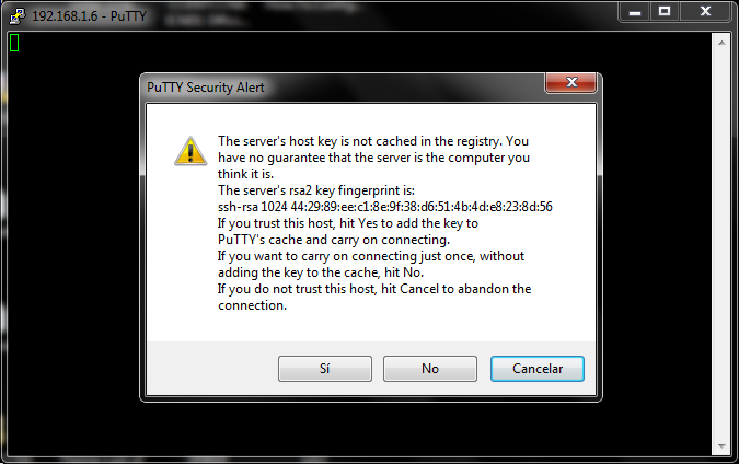
Utilizamos PuTTy para iniciar sesión en SSH, al conectarnos nos mostrado un dialogo para aceptar el certificado tal como se muestra en la siguiente imagen.

Una vez aceptado el certificado, iniciamos sesión con nuestro nombre de usuario y contraseña.

Configuraciones Básicas de un Router o Switch Cisco

En este post se mostrara como realizar las siguientes configuraciones básicas de un Router Cisco.
  • Configurar un Nombre al Router
  • Configurar los Passwords
  • Proteger los Puertos de Consola y el Auxiliar
  • Configurar un Banner
  • Encriptar Passwords
  • Como guardar la Configuración
También quiero mencionar que los comandos que se utilizaran para configurar el Router son los mismos para un Switch Cisco.

Configurarle un Nombre al Router

Para configurarle un nombre al router se utiliza el comando hostname.

Escribimos enable para entrar a Modo Privilegiado (Privilege Exec Mode)
Router> enable
Escribimos Configure Terminal para entrar a Modo de Configuración Global (Global Configuration Mode)
Router# configure terminal
Una vez en configuración global escribimos el comando hostname y el nombre del router.
Router(config)# hostname nombredelrouter
Ejemplo
Router>
Router> enable
Router# configure terminal
Enter configuration commands, one per line.  End with CNTL/Z.
Router(config)# hostname delfirosales
delfirosales(config)#

Configuración de las Contraseñas

Son cinco las contraseñas que se utilizan para asegurar nuestros router Cisco.
  1. Consola
  2. Auxiliar
  3. Telnet (vty)
  4. Enable Password
  5. Enable Secret
El enable secret y enable password se utilizan para asegurar con una contraseña al modo privilegiado. Esto hará que un usuario escriba el comando enable le pida una contraseña y así entrar a modo privilegiado. Los otros tres se utilizan para configurar una contraseña cuando el modo de usuario (User Exec Mode) se accede a través del puerto de consola, a través del puerto auxiliar o a través de Telnet.

Enable Password y Enable Secret

Para habilitar el enable password y el enable secret tenemos que estar en modo de configuración global, como se muestra a continuación.
delfirosales# configure terminal
Enter configuration commands, one per line.  End with CNTL/Z.
delfirosales(config)# enable ?
last-resort Define enable action if no TACACS servers respond
password    Assign the privileged level password
secret      Assign the privileged level secret
use-tacacs  Use TACACS to check enable passwords

delfirosales(config)# enable password delfirosales
delfirosales(config)# enable secret delfirosales
The enable secret you have chosen is the same as your enable password.
This is not recommended.  Re-enter the enable secret.
Hemos configurado los el enable password y enable secret, pero hemos recibido un mensaje en consola de que la contraseña utilizada para el enable password y enable secret es la misma, asi que lo recomendable es cambiarla, utilizar contraseñas diferentes.
delfirosales(config)# enable secret delfi
delfirosales(config)#
Configurar una contraseña al Puerto Auxiliar

Para configurar una contraseña al puerto auxiliar tenemos que estar en modo de configuración global.
delfirosales# configure terminal
Enter configuration commands, one per line.  End with CNTL/Z.
delfirosales(config)# line aux 0
delfirosales(config-line)# password passaux
delfirosales(config-line)# login
delfirosales(config-line)#
Configuara un Password para la Consola
delfirosales(config)# line console 0
delfirosales(config-line)# password passconsole
delfirosales(config-line)# login
delfirosales(config-line)#
Configurar un Password a Telnet

Para configurar un password a telnet necesitamos estar en modo de configuración global y utilizar el comando line vty. Todos los router que no estén ejecutando la edición Enterprise del IOS por defecto solo tienen cinco líneas vty, de la 0 a la 4. Pero si nuestro router esta ejecutando un IOS de la edición Enterprise, tendremos mas líneas vty. La mejor manera de averiguar el numero que tiene el router utilizaremos el signo de interrogación como se muestra a continuación.
delfirosales(config)# line vty ?
<0-1276>  First Line number

delfirosales(config)# line vty 0 1276
delfirosales(config-line)# password passtelnet
delfirosales(config-line)# login
delfirosales(config-line)#
Banners

Los banners son mensajes de advertencia que se muestran cuando alguien quiera establecer una sesión de telnet. Para configurar el banner mas utilizado, el banner MOTD (Message of the day) escribimos en consola el siguiente comando.

(config)# banner motd x Aquí el mensaje del Banner motd x
Por ejemplo
delfirosales(config)# banner motd x Prohibido el Acceso no Autorizado! x
Cerramos sesión y al tratar de iniciar una sesión nueva nos saldrá el mensaje motd como se muestra a continuación.
delfirosales(config)#
delfirosales(config)# ^Z
*Mar  1 00:45:21.963: %SYS-5-CONFIG_I: Configured from console by console
delfirosales# exit
Después de todo podemos comprobar con el comando show running-config que todo esté bien

Con el comando show running-config podremos ver todo lo que hemos configurado en el router, pero como se muestra la imagen las contraseñas del puerto auxiliar, la de consola y las de telnet se pueden ver claramente asi que tenemos que encriptarlas.

Encriptar los Passwords

Debido a que solo la contraseña de enable secret se encripta de forma predeterminada, tendremos que encriptar las contraseñas manualmente utilizando el comando service password-encryption desde configuración global.
delfirosales# config t
Enter configuration commands, one per line.  End with CNTL/Z.
delfirosales(config)# service password-encryption
Con este comando todas las contraseñas se encriptaran, tal como se muestra en la siguiente imagen.

Guardar la Configuración

Finalmente después de configurar nuestro router ahora toca guardar la configuración de la running-config a la startup-config.
delfirosales# copy running-config startup-config
Destination filename [startup-config]?
Building configuration...
[OK]
delfirosales#
En otro post veremos otras configuraciones de los equipos cisco. Saludos!
Este vídeo muestra cómo instalar GNS3 en Ubuntu 10.10. GNS3 es un simulador gráfico de red que te permite diseñar topologías de red complejas y poner en marcha simulaciones sobre ellos.

GNS3 v0.7.3
http://www.gns3.net/download
Dynamips
http://www.ipflow.utc.fr/blog/?p=52

GNOME Terminal
gnome-terminal -t %d -e 'telnet %h %p' >/dev/null 2>&1 &

Video Online
http://www.youtube.com/watch?v=lqVfdOTFPgM

Interface Loopback + Cisco SDM (Security Device Manager) en GNS3

Este vídeo muestra como instalar una interface Loopback en Windows 7 y después realizar una conexión con un router simulado en GNS3. Tambien se muestra como configurar el router para poder acceder desde el Security Device Manager (SDM).

SDM (Security Device Manager) es una herramienta de configuración basada en el explorador web que simplifica la configuración y las funciones de seguridad de un router a través de asistentes de forma facil y rápida sin conocimientos de la interfaz de linea de comandos (CLI).

Comandos

Configurar una IP al Router y verifica el estado.
R1# configure terminal
R1(config)# interface FastEthernet0/0
R1(config-if)# ip address 192.168.1.6 255.255.255.0
R1(config-if)# no shutdown
R1(config-if)# exit
R1(config)# exit
R1# show ip interface brief
Habilitamos el HTTP en el Router y creamos un usuario con sus respectivos privilegios
R1# configure terminal
R1(config)# ip http server
R1(config)# ip http secure-server
R1(config)# username delfirosales password cisco123
R1(config)# username delfirosales privilege 15
R1(config)# ip http authentication local
R1(config)# exit
R1# wr
Probando la Conectividad.
R1# ping 192.168.1.5

Type escape sequence to abort.
Sending 5, 100-byte ICMP Echos to 192.168.1.5, timeout is 2 seconds:
.!!!!
Success rate is 80 percent (4/5), round-trip min/avg/max = 4/15/48 ms
Una vez probada la conectividad, podremos acceder al SDM desde el navegador.

Video Online
https://www.youtube.com/watch?v=8skBKbZzXP0

En este vídeo se muestra como instalar GNS3 en Windows 7, es el segundo vídeo de varios que quiero realizar para ayudar a los demás que tienen problemas con GNS3, después realizare algunos vídeos básicos sobre esta misma herramienta.

En resumen lo que se muestra en el video son los siguientes temas.
Video Online
http://www.youtube.com/watch?v=jdesSM5upAY

En este vídeo muestro cómo solucionar un defecto de GNS3 cuando se crean proyectos y éste no guarda el archivo de configuración inicial o startup_config de un router Cisco.

Video On-line:
http://www.youtube.com/watch?v=LQ0W0oOLKhk

Commandos
R1#show run
R1#show ip interface brief
R1#configure terminal
R1(config)#hostname delfirosales
delfirosales(config)#interface f0/0
delfirosales(config-if)#no shutdown
delfirosales(config-if)#ip address 192.168.1.1 255.255.255.0
delfirosales(config-if)#end
delfirosales#show ip int brief
delfirosales#wr

Instalar GNS3 en Ubuntu 9.10

He pasado un buen rato tratando de instalar gsn3 en ubuntu, es por eso que he decidido crear este post para mostrar los pasos que realice para instalar GNS3 v0.7RC1 en ubuntu 9.10.

¿Cómo instalar GNS3 en Ubuntu 9.10 ?

Abrimos la consola y agregamos lo siguiente.

sudo aptitude install build-essential libelf1 libelf libpcap0.8 libpcap0.8-dev python-dev, python-Python apoyo configobj python-qt4 estiba


Descargamos GNS3 del siguiente enlace http://www.gns3.net/download (Descargamos GNS3-0.7RC1-src.tar.gz)

Una vez descargado el archivo anterior lo extraemos dando clic derecho y "Extraer aquí" o igual puedes hacerlo desde consola con el siguiente comando

tar zxf GNS3-0.7RC1-src.tar.gz

Esto creara una carpeta llamada GNS3-0.7RC1-src.

Ahora pasamos a descargar el Dynamips desde la siguiente pagina http://www.ipflow.utc.fr/blog/ Descargamos 0.2.8-RC2 binary for Linux x86 platforms

Una vez descargado Dynamips hacemos clic derecho en el archivo descargado "dynamips-0.2.8-RC2-x86.bin" y seleccionamos Propiedades, en la sección de permisos activamos la opción "Permitir ejecutar el archivo como un programa" tal como se muestra en la siguiente imagen.


imagen permisos de ejecución.

Ahora desde la consola nos vamos al directorio donde extraimos GSN3, en mi caso GNS3-0.7RC1-src y ejecutamos el siguiente comando.

sudo python setup.py install


Nos dirigimos a la carpeta donde extraimos GSN3, en mi caso GNS3-0.7RC1-src, ahí encontraremos un archivo llamado gsn3, solo hacemos doble clic en el archivo y nos saldrá un recuadro preguntando que hacer, seleccionamos "Ejecutar" esto iniciaría GSN3, también podemos hacerlo desde consola ejecutando "./gns3".


Toca configurar la direccion donde tenemos el Dynamips (dynamips-0.2.8-RC2-x86.bin), para esto podemos dar clic en el numero 1 (step 1) del Menu que se nos presento por primera vez al ejecutar GSN3 o desde el Edit - Preferencias - Dynamips de GSN3.

En la sección de Ruta del ejecutable seleccionamos donde tenemos el archivo descargado "dynamips-0.2.8-RC2-x86.bin", una vez hecho esto hacemos clic en "Prueba" o test, si toda va bien tiene que aparecer un mensaje en verde "Dynamips Successfully started" tal y como se muestra en la siguiente imagen.


Ahora toca agregar las imágenes IOS para esto hacemos clic en el paso 2 (step 2) del menu que se nos presento por primera vez, o desde el menu Edit - Imagenes IOS e Hypervisors.

En la sección Image file seleccionamos la ubicación de la imagen IOS que deseamos agregar y hacemos clic en Save, tal como se muestra en la siguiente imagen.


En esta sección podemos agregar mas imágenes IOS, en mi caso solo agregue una imagen de un router 7200. Una vez hecho esto ya tenemos listo para empezar a emular imágenes IOS.


Realice un vídeo en el que se muestra como instalar GNS3 en ubuntu 9.10, puedes verlo en los siguientes enlaces.

Video - Instalación de GNS3 v0.7 RC1 en Ubuntu 9.10
http://delfirosales.blogspot.com/2010/02/video-instalacion-de-gns3-en-ubuntu.html